

Stag
(1970-1977)
One of the Least Well Known
The Stag is one of the least well known Triumphs imported to the United States. The Stag was a wonderful concept, but sales suffered primarily due to problems with the maintenance of the newly designed Triumph V-8: a 3.0 litre overhead camshaft engine.

A Brief History of the Stag
Market launch date in the UK was in April or May of 1970, now commonly referred to as the Mark I Stag. Mark I Stags had downward pointing gauge needles among other distinguishing features.
US-market Mark I Stags were introduced in September of 1971. The US version had lower-power, emission control, and side marker lights with a “Stag” badge under the rear side light.
Mark II Stags were introduced in February of 1973. Along with some cosmetic changes, gauges now pointed up, seats were changed, the air filter was different, compression was lowered, steering ratio was changed and a smaller steering wheel was fitted.
The Stag was available either with a 4-speed (with overdrive) manual or 3-speed automatic transmission. An “A” Type overdrive (0.82:1) was fitted up to chassis number LD21230 (LE20856 in the US). This was changed to a “J” Type overdrive (0.797:1) starting with chassis number LD21231 (LE20857 in the US). All US automatic transmission-equipped cars were fitted with a Borg-Warner Type 35 transmission. Other markets used the Borg-Warner Type 35 up to chassis number LD41993. Starting with chassis number LD41994, this was changed to a Borg-Warner Type 65 transmission.
Importation to the US market ended after 17 months in July of 1973. Production for other markets continued until June of 1977.


Member Pages
David Sims | (Chelmsford, UK)
If you would like your page added to this listing, please contact the webmaster.
Production Dates and Numbers
The Triumph Stag was produced from 1970 until 1977. The Stag was only imported into the United States from 1971 through 1973. Most of the exported Stags went to the United States. Production continued in the U.K. until 1977 with a total of 25,877 Stags being produced all together.
Source: Triumph factory data


Stag Buyer’s Guide
Updated by Tim Buja
In addition to the items listed in the general Triumph Buyers Guide, there are a number of specific items of interest on the Stag.
The Stag engine has proved to be its great weakness. Some people have even christened it the “Triumph Snag”. The key problem with the Stag is its cooling system. To test it, you should let any potential purchase idle for 15 minutes (preferably on a hot day) while keeping an eye on the temperature gauge. Check that the radiator is as hot at the bottom as it is at the top. If it’s not, there may be problems with coolant circulation and expensive damage may have already been done. In addition, check that the thermostat (in the intake manifold) hasn’t been removed to mask some chronic cooling problem, and make sure that the oil pressure light is connected. If not, leave well enough alone.
An overheating Stag will eventually end up with a warped head. Like the TR7 (which uses half of the Stag V8), Stag heads have a bad reputation for warping in service, often with as few as 25,000 miles. The blown gaskets which soon follow can lead to damaged head faces which will need skimming if they are to be rescued. The trouble is that Triumph only allowed 0.010″ for removal before the head had to be replaced. In some cases, this is still not enough to save the head. A blown head gasket can also cause engine coolant to seep between the head and the studs. An electrochemical reaction between the aluminum head and the steel studs causes the head studs to seize in place, making head removal almost impossible since the studs and bolts used to attach the head to the block are not parallel. Some people have had to lift the car with an engine hoist and pound on the head studs with an air hammer, using the weight of the car to pull the studs through the head. Internal corrosion of the coolant passages is another problem if a corrosion-inhibiting coolant was not used.
Mark II Stags originally came with a sheet metal radiator fan cowling to increase the efficiency of the radiator cooling fan. Many of the cowls were removed when the original engine mounts sagged, causing the engine driven radiator fan to rub against the cowl. Removal of the cowl solved the noise problem, but may have created an overheating problem. If your Stag doesn’t have a radiator fan cowling, new composite cowls are now available. Visit the Triumph Stag Composite Radiator Cowl page for more information. Be aware that while these parts were modeled from a genuine MkII Stag cowling, they are being produced from composite polyester/fiberglass instead of the original sheet metal, and are not British Motor Heritage approved. If you have a 16.5″ metal radiator fan, you should plan on replacing both of the front engine mounts to eliminate the possibility of the fan striking the cowl or the lower radiator hose. This is a major job – replacing the right engine mount requires you to remove the alternator, which requires removal of the anti-sway bar and automatic transmission oil cooler. Changing the left engine mount will require you to remove the exhaust manifold.
Timing chains are another source of concern. The single-roller chains wear quickly and should be replaced every 25-30,000 miles. If they break or skip a tooth, the valves will embed themselves in the pistons. The hydraulic timing chain tensioners are actuated by the engine lube oil, so you must keep the idle rpm up high enough to maintain sufficient oil pressure. If you hear the timing chains rattle when you start the engine, but the noise goes away a few seconds later as the oil pressure comes up, plan on replacing the timing chains within the next 3000-5000 miles. If the rattle doesn’t go away at idle, don’t drive the car any further or you’ll be facing a major repair bill in the very near future. You don’t want to see the oil light come on at idle, since it means you have less than 5psi of oil pressure.
Along with the TR7 engine, the Stag engine has a jackshaft that runs in the block. This shaft drives the water pump, distributor and oil pump. Both engines have shown a tendency to wear the bottom of the front jackshaft bearing surface in the block. This results in reduced oil pressure, and eventually, a seized jackshaft. A preliminary symptom of excessive front bearing wear is the failure of the water pump drive gears due to insufficient lubrication splashing out from the front jackshaft bearing. Some people simply replace the jackshaft and water pump, not realizing the root cause of the problem is the worn front jackshaft bearing. The only fix for this is to completely strip the engine and have the jackshaft bearings align-bored and resleeved. This wear is not apparent until the engine is torn down, and even then, some experienced engine rebuilders have missed it. The lack of an engine oil pressure gauge makes this problem even harder to spot.
There was a brief period when crankshaft bearings wore out prematurely due to a temporary machining problem which resulted in the wrong surface finish on the crankshaft journals. If you have to regrind the crankshaft, make sure that it is properly hardened afterwards or you’ll have a disaster in a very short time. Since the original factory hardening process only penetrated around 10-15 thousandths below the surface, you may remove all of the hardened surface with the first regrind. Premature wear could also occur as a consequence of poor maintenance, or if the engine (and hence, the oil) was running too hot as a consequence of cooling problems.
The source of any fluids found on the top of the engine can be checked by cleaning the top of the engine with a pressure washer (or at a self-service car wash). Drive the car until it is hot enough to evaporate any water left on top of the block. When the engine is dry, place a couple of white paper towels between the intake manifold and the top of the block and let it sit for several hours. Coolant (green) may appear from a number of sources. A leaking water pump seal will cause coolant to leak out of an opening below the waterpump cover, on the flywheel side of the waterpump housing. The intake manifold gaskets are supposed to seal the fuel/air mixture flowing from the manifold into the heads, as well as coolant flowing from the heads into the manifold. These gaskets are notorious for allowing coolant leaks. Other coolant leak sources could be from the thermostat cover, bypass hose, or heater return hose. The water pump cover gaskets are well designed and rarely, if ever, leak. Fuel leaks may be from improperly adjusted carburetor floats or leaking needle valves. Oil leaks are probably from the camshaft cover gaskets.
Test for suspension bushing wear in the usual manner by shaking each wheel sideways while a helper applies the brakes. If there is play, the suspension bushings may need to be replaced; if there is play with the brakes off, then suspect a wheel bearing.
A trait common to Triumphs with semi-trailing arm rear suspension (Triumph 2000/2500, TR4A IRS, TR5, TR250, TR6) has developed the name “Triumph Twitch”. This is a curious sideways lurch at the rear when you let off the throttle in the middle of a turn. This lurch doesn’t always happen, but when it does, it’s caused by the splines of the telescopic drive shafts sticking under power and then freeing in coast, thereby locking, then releasing the rear suspension. The official word from Triumph was that this is a lubrication problem that should not arise, though they did admit that it sometimes does occur. Contrary to popular opinion, the lurch is not caused by worn semi-trailing arm bushings. Several Stag parts houses in the UK have developed replacement halfshafts that use modern constant velocity joints that provide articulation, as well as compression and extension without the use of sliding splines. These new halfshafts eliminate the Triumph Twitch, but at a price – expect to pay $600+ for a pair!
Like the TR6 that shares its manual gearbox, the Stag has a reputation for wearing out its synchromesh in second and third gears. They also tend to suffer from gearlever buzzes after a lot of use. The automatic transmission (Borg-Warner Type 35) tends to engage Reverse and Drive with a lurch if the idle speed is set too high. This problem can also be accentuated by worn driveshaft U-Joints. Reluctance to shift at speed can be caused by a poorly adjusted downshift cable. A metallic ping from the propellor shaft can be heard if the differential input flange bolts are loose. The differential has a good reputation, although they tend to whine as they age. Most new differentials whine from day one because a recent batch of ring & pinions appear to have been improperly hardened. Another source of drive line noise can come from the quill shaft bearing in the differential’s pinion extension housing. If the differential pinion oil seal fails, the differential oil will flow into the extension housing and wash away the grease for the quill shaft bearing. A visible oil leak from the pinion flange area could mean future trouble.
Power steering leaks may occur, but no more than on any other power-steered car. Inspect the rack gaiters for signs of oil leaks. Type F Automatic Transmission fluid should be used to top up the reservoir. If the rack leaks, it’s best to have it professionally rebuilt. Replacement seal kits are available, but it seems that DIY repairs don’t last long enough to be worth the trouble of doing it yourself. Note that the power steering pump must be unbolted to remove the battery, although the hoses stay connected.
Brake troubles are rare. The convertible storage hold can leak, and if the top was not stored correctly, it can be very difficult to erect. Before the top is lowered into the hold, the rear section must be locked in the vertical position using the two latches provided. Failure to do this will cause the rear section to become trapped in the hold, although instructions are provided in the owner’s manual on how to extract it.
The tinworm can and does attack the Stag, and you should look for rust damage in the floorpan, fenders (inner and outer), rear fender/sill joints, rear subframe mountings, and the outriggers. Check these areas very carefully, for while replacement panels are available, they are expensive. It seems that post-1974 Stags are more susceptible to rust problems than are the earlier models due to the factory switching to a different sheet steel supplier.
Proper and timely maintenance is crucial for the longevity of a Stag. If you already own one, keep these tips in mind. If you’re looking to buy one, read the following and then ask the owner about how it was maintained.
The most important maintenance item on a Stag is an annual reverse flush of the cooling system, followed by replacing the coolant with a good quality anti-freeze with the proper corrosion inhibitor for aluminum engines. See the Annual Cooling Flush article for complete details. The flush will also help to remove the last bits of casting sand from the water passages in the block. This should be followed up by weekly (or even more frequent) checks of the coolant level in the expansion tank. You must maintain the correct coolant level, since the gear-driven water pump is mounted high in the engine. Even a small loss of coolant will drop the level below the point needed to maintain circulation.
While you’re changing the engine coolant, inspect all of the coolant hoses. For the last few years, OEM style reinforced hoses have been unavailable, and the only alternative was to use un-reinforced hoses. These hoses do not meet the construction standards set by British Standard Specification 5119, which covers automotive coolant hoses and states that all hoses used on cars must be reinforced. While the hose manufacturer claims that un-reinforced hoses are suitable for the Stag, the elevated temperatures and pressures present in the Stag’s engine compartment make them marginal, at best. Even if your reinforced hoses appear in good condition, replace them every five years or 25,000 miles, whichever is sooner. If your Stag has overheated, replace them sooner. Always wipe off any gasoline, oil or solvent contamination as soon as possible. Unreinforced hoses should be replaced if they balloon when hot, or take a permanent balloon when cold. Since the wall thickness of unreinforced hoses is more inconsistent than reinforced hoses and tend to be thinner on the outsides of bends, there is a higher failure rate at these points. Carefully inspect these hoses on the outside of the bends, using thumb pressure to check for variations in the wall thickness. Reinforced coolant hose sets are now available again, starting at $40 and up.
Next, plan on changing the oil and filter every 3,000 miles and checking the timing chains every 25,000 miles. Once they start to rattle, there’s a danger of jumping a tooth or breaking a chain. The Stag engine is not a freewheeling design – the pistons will collide with open valves if a timing chain breaks or if the camshaft timing is off. These destructive encounters between valves and pistons are very expensive…
It’s important to keep the rear axle breather clear. Clogging here can cause the oil to overheat and escape through the seals, with the consequent danger of seizure. The breather is on the top of the differential casing, near the right rear corner. Check that the pin is loose in the breather hole.
Driveshafts need a regular shot of the correct grease to keep the sliding splines from becoming worn, or in the worst case scenerio, seized. Replacements are expensive.
If there are any signs of overheating from whatever cause, do not attempt to drive any further. The Stag, with its very heat-sensitive alloy heads and lubrication system, will not see you to your destination before suffering expensive engine damage.
Here are a number of Stag parts sources. (Note: this list of vendors is not in any particular order, and none of these have been endorsed by the Vintage Triumph Register as being any better or worse than any other listed or non-listed vendor. If you know of any other Stag parts vendors, please let us know!)
Note: this section is still under construction, so several of the telephone numbers have not been included here. They will be added to this list when their accuracy has been verified.
| US Vendors: | Telephone # | Fax # | Location |
| Eightparts | 520 670 9377 | 520 670 9080 | Tuscon, Arizona |
| Stag Specialists | 520 792 0294 | 520 746 1336 | Tucson, Arizona |
| UK Vendors: | Telephone # (from US) | Fax # | Location |
| Abinger Hammer Motors | 011 44 1306 730427 | Dorking | |
| Aldridge Trimming | 011 44 1902 710805 | 011 44 1902 27474 | Wolverhampton |
| Brighton Stag Specialist | 011 44 1273 700861 | same | Hove, East Sussex |
| Cardinal Triumph Supplies | 011 44 191 478 5444 | 011 44 191 478 4739 | Gateshead, Tyne & Wear |
| James Paddock Sportscars | 011 44 1244 676827 | 011 44 1244 676877 | Saltney, Chester |
| HRS Garages | 011 44 181 963 1080 | 011 44 181 963 0946 | London |
| Peak Performance Co. | 011 44 181 570 0477 | 011 44 181 570 7037 | Middlesex |
| Rimmer Brothers, Ltd | 011 44 1522 568000 | 011 44 1522 567600 | Lincoln |
| SOC Spares Ltd | 011 44 1622 891777 | 011 44 1622 891678 | Kent |
| Spectrum Auto Services | 011 44 181 670 9639 | London | |
| T.D. Fitchett | 011 44 1952 619585 | 011 44 1952 610510 | Telford |
| The Stag Centre | 011 44 1279 793434 | same |
The Stag shared many of its parts with other Triumphs, so you can get Stag parts even from vendors that don’t otherwise support it. The following is an incomplete list of part numbers followed by a short description of how other Triumph models used the same part.
P/N Stag Part Description Cross-Reference
GFE1040 Air Filter TR7 Air Filter
GFE147 Oil Filter Element TR7 Oil Filter Element
GDC117 Distributor Cap TR8 Distributor Cap
GBP242 Front Brake Pads TR8 Front Brake Pads (80-81)
137599 Trailing Arm Bushings TR6 Trailing Arm Bushings
TKC1887 Coolant Expansion Bottle (72-on) TR7 (75-78) Expansion Bottle
TKC101 Viscous Fan Coupling (Mk II) TR7 Viscous Fan Coupling
143257 Crankshaft Timing Chain Sprocket TR7 Crankshaft Timing Chain Sprocket
151089 Timing Chain Tensioner TR7 Timing Chain Tensioner
145017 Water Pump Cover Gasket .010 TR7 Water Pump Cover Gasket .010
149852 Water Pump Cover Gasket .020 TR7 Water Pump Cover Gasket .020
149853 Water Pump Cover Gasket .030 TR7 Water Pump Cover Gasket .030
GWP206 Water Pump (12 Vane) TR7 (77-on) Water Pump
GWP207 Water Pump (6 Vane) TR7 (75-77) Water Pump
(Note: While the 6 and 12 vane water pumps are interchangeable, the covers are not. If you replace a 6 vane pump with a 12 vane pump, you must also install the 12 vane cover, p/n 218542.)
Several recent magazines have had articles on the Stag. Try looking here for additional information:
- “Stag Double Feature” – Triumph World, October/November 1996
- “Your Cars – 1971 Triumph Stag Restoration” – Practical Classics, July 1996
- “Best Buy – Triumph Stag” – The complete guide to the family man’s classic – Classic and Sportscar, May 1996
- “The X.815 File” – Triumph Stag Fastback Prototype – Triumph World, April/May 1996
- “Stag V8” – Be an engine expert – Practical Classics, April 1996
- Thoroughbred & Classic Cars, February 1996
- “Seasider” – Triumph World, April/May 1995
- “Counting the Cost” – Restoring a Triumph Stag – Thoroughbred & Classic Cars, August 1990
Some books worth noting:
- Triumph Stag: The Complete History, by James Taylor and Dave Jell – Windrow & Greene
- Triumph Stag 1970-1980 road test reports – Brooklands Books
- Triumph Stag: Choice, Purchase & Performance, by James Taylor – Windrow & Greene
- Practical Classics Triumph Stag Restoration – Kelsey Publishing
You can get help from other Stag owners via Internet Email. The Stag mailing list currently has about 100 members. You can subscribe to either the “stag” list, which sends mail out as soon as it receives it, or to the “stag-digest” list, which sends out one message per day with all of the previous day’s postings. For more information about the Stag mailing list or to view the archives of past postings, visit the Stag Mailing List home page.
You can also join a more general mailing list for just Triumphs or for all British cars in general. To do so, send a note to majordomo@autox.team.net and put (without the quotations):
“subscribe triumphs”, “subscribe british-cars”, or “subscribe british-cars-digest”
in the body of the message. Be aware that around 1200 people are on the british-cars list, and there can be an incredible amount of traffic each day. Information on all of these mailing lists (and many more) can be found at http://www.team.net/sol/sollists.html
Stag Maintenance Guide
- Carburetor Tuning Using Colortune®
- Tuning and Improving the Ignition System
- Keeping Your Stag Cool
- Tips for the Maintenance of Wheels
- Setting the Idle Speed
- Head Tension
- Elec-trickery
by Tim Buja, TKBuja@insightbb.com
Setting the air-fuel mixture using a Colortune involves replacing the spark plug in one of the cylinders with the special Colortune plug. The Colortune plug has a transparent window that allows you to see the flame color in the cylinder as it fires. An overly rich mixture will have a yellow flame and will be accompanied by black smoke (and noxious fumes) from the tailpipes. As you lean it out to the optimum stoichiometric mixture, the flame color will change to Bunsen blue. A mixture that is too lean will still have a blue flame, but the brightness will decrease as the mixture is weakened. If the piston dampers in each carb are working correctly, you should see the flame color change from blue to yellow when you open the throttle, and then change back to blue as the engine comes up to speed. Read the Colortune instruction sheet for full details on how the system works.
In order to set the air-fuel ratio correctly, you need to know which carburetor feeds which cylinder before you can start making adjustments. In this section, all references to “right” or “left” are made when sitting in the driver’s seat looking toward the front of the car.
The Stag V8 engine is fed by two Zenith Stromberg 175CD SEV carburetors mounted on a two-plane manifold. The right carburetor feeds the lower plane, which connects cylinders 1, 4, 6, and 7. The left carburetor feeds the upper plane, which connects cylinders 2, 3, 5, and 8. There is a small balancing passageway that connects the two manifold planes, so you may see some small effects of adjusting one of the carbs in a cylinder not directly connected to it. Be aware that the cylinders in the Stag V8 are not numbered per the standard method (#1 at the left front), as illustrated in the figure below:
front of car
cylinder cylinder Key: L: Left Carb
l #2 #1 r R: Right Carb
r #4 R #3 l l: Cylinder fed by left carb
r #6 L #5 l r: Cylinder fed by right carb
l #8 dist #7 r dist: Distributor
Firing Order:
1 – 2 – 7 – 8 – 4 – 5 – 6 – 3
Note that the #2 (left front) cylinder is used to set the ignition timing, not the #1 cylinder as in most other engines.
Colortune® is a registered trademark of Gunson’s Ltd., Pudding Mill Lane, London E15 2PJ
This section was written by William Mayo and Walter Holliday,
originally appearing in Issue 38 of The Vintage Triumph magazine (currently out of print)
HTML version by Tim Buja, TKBuja@insightbb.com
The importance of a sound ignition system to the running of a car cannot be overstressed. This is particulaly true of the Stag, whose high-revving V-8 and twin-point distributor create special challenges.
The heart of the ignition system is the distributor – Lucas in the case of the Stag. The Lucas distributor is as reliable as any, provided it is given proper maintenance. This is actually quite simple and will reward the owner with increased distributor life and enhanced reliability, performance, and economy.
To service the unit, one needs only a small oil can, a tube of Bosch point lube (or similar), and a thin-blade screwdriver. Removal of the unit and major service require, in addition, a 1/2″ and 7/16″ combination wrench, and a Phillips screwdriver.
Before maintenance can be performed, one must first ascertain the condition of the unit through a thorough inspection. Carefully pry back the cap retaining clips by hand or with the aid of a screwdriver. Once off, rotate the ignition rotor counterclockwise to the full extent of its travel. If the rotor does not return to the home position, or is slow to return, the centrifugal advance mechanism is probably gummed up or dirty. Lubrication may solve the problem, and as this can be done “in situ”, it should be tried first. If cleaning is necessary, removal of the unit is required. Ensure also that the rotor is tight to the shaft. If it can shift back and forth on its own, the rotor key is worn and the rotor needs replacing. The operation of the vacuum advance, retard, or advance/retard mechanism should also be checked. [See Setting the Stag Idle Speed for additional information on this topic.] On Stags an incredibly high number of these units are defective or perished. This results in a poor idle and power curve as the car is relying entirely on the centrifugal advance and has a vacuum leak as well. To check the unit, follow the hose or hoses to the vacuum pick-up on the carb or manifold and remove it at this point. Leave it attached to the distributor. Examine the hose for cracking or brittleness and replace it if perished. It is of common size and can be obtained at an American (for the Stag, “foreign” parts house. After inspecting or replacing the hose, suck on the end of it and observe the resulting movement in the distributor. One of the following results should occur: (1) If no vacuum is built up, the vacuum unit has a hole in the diaphragm and needs to be replaced. (2) If vacuum is built up, but leaks down when you block the tube with your tongue, the diaphragm has a small hole in it and still needs to be replaced. (3) If vacuum is built up, but the plate refuses to move or moves sluggishly and sticks, lubrication and/or cleaning are required. (4) If the plate moves, then returns when you release vacuum, it is functioning properly.
Next, we remove the rotor and try to move the shaft side-to-side in order to check the condition of the distributor bushings. If this movement exceeds .002 to .003″, the bushings are worn out. Worn bushings cause irregular dwell, poor idle, and poor running. If worn out, the distributor must be rebushed, replaced, or an electronic ignition may be fitted.
Assuming the distributor has passed muster, we can lubricate it. The distributor is not self-lubricating (except for the lower bushing). Lubrication should be done sparingly and often (approximately every 3000 miles). Excessive oil or grease will be spattered on the points causing them to burn. Apply two drops of oil to the spindle bushing by way of the large screw located directly under the rotor. (There may be a felt pad on top of this screw to retain the centrifugal advance weights.) Apply one drop to each point pivot pin and one or two drops to the collar where the breaker plate and the lower plate contact. Smear a bit of the point lube on the cam faces (the area where the points touch the spindle). DO NOT use Vaseline or other types of grease as they will spin off the cam from the heat and centrifugal force. Other brands of point lube (such as GM) can be used if the Bosch type is not readily available. Also, smear a small amount on the distributor cap/body interface. This will seal out water, thus preventing cross-firing or grounding in moist conditions. Wipe off any excess oil or grease and carefully examine the cap and rotor before returning them to the distributor.
Examine the firing tip of the rotor for burning, the center of the rotor (where the carbon rod touches) for wear, and the key to make sure that the rotor will not rotate on the shaft. Check the cap electrodes for burning and the cap in general for minute cracks or carbon tracking. Any of these condition can cause misfiring under certain condition. Finally, check the center carbon electrode for wear. This is a common occurrance on the Stag. The new length is approximately 1/2″. If it protrudes less than 1/8″, it is time to replace the cap. When the electrode wears to the point that it no longer touches the rotor, the rotor will develop a cratered appearance from arcing. The rotor will also have tiny arc marks on it. At this point, performance will be seriously affected. Since the cap (Unipart GDC117) is fitted to very few other cars (TR8, Rover, and some Roll-Royce), the prudent owner should carry a spare in the trunk.
If distributor removal is necessary, i.e., to replace the vacuum unit, rebush the shaft, or to install electronic ignition, this can be done after removing the coil with a 7/16″ wrench. The coil must also be removed to set the timing, unless using factory tool S349. Before removing the distributor, align the engine at TDC and mark the position of the rotor with a small scratch on the distributor body to aid reinstallation. Do not rotate the engine with the distributor removed or you will lose the ignition timing.
This section was written by William Mayo and Walter Holliday,
originally appearing in Issue 38 of The Vintage Triumph magazine (currently out of print)
Section in brackets [] added by Tim Buja, TKBuja@insightbb.com
The Stag needs all the help it can get in order to prevent boiling over. Most Stags have the familiar hexagon-shaped brass plug on top of the radiator; early models had the American style pressure relief cap. During periods of peak pressure, coolant is allowed to run into the plastic collection bottle. Because most of these bottles were fitted with pressure caps rated at only 13 lbs. per square inch, we strongly recommend the use of 20 lb. caps which became standard on later model Stags. If your dealer can provide one, it is Unipart # GRC124.
Equally important is the use of a good thermostat. Never attempt to operate the car without one. The principal behing the “pump-assisted, thermo-siphoned” cooling system is that coolant remains in the radiator long enough to be cooled before returning to the engine. The thermostat regulates this flow. In addition, it provides a very necessary build up of pressure because the water pump works best when it assists the flow of coolant already in motion.
[Be sure that you have the correct type of thermostat. To improve drivability and shorten the engine warm-up time, the Stag has a bypass port behind the thermostat which connects the water pump suction line to the intake manifold coolant chamber. Since it collects all of the coolant flow from the engine through both of the cylinder heads, the intake manifold coolant chamber is the hottest part of the cooling system. The heated manifold prevents fuel from condensing on its inner walls and causing drivability problems like lean stumble. The bypass port allows the manifold to heat up faster by allowing coolant to flow into the water pump via the intake manifold coolant chamber as the engine warms up. In addition to the manifold chamber passageway, coolant can also flow from the left cylinder head through the heater control valve and heater core to the water pump. If the heater valve is closed, there won’t be any flow through this path, leaving the bypass port as the only path for coolant flow into the water pump when the engine is cold.
As the engine comes up to normal operating temperature, the thermostat should close off the bypass port as it opens the main discharge line to the upper radiator hose (hot side of the radiator). Most thermostats do not have the blanking disk that closes this bypass port. If you use one without the blanking disk, the water pump will take suction from both the hot and cold sides of the radiator. In addition to raising the temperature of the coolant pumped back into the engine, this will reduce the volume of coolant flowing through the radiator.

This picture shows the Unipart GTS 101 (left), Robertshaw 412-180 (center), and for comparison, a “normal” thermostat as used in Triumph six cylinder OHV engines, Spitfire four cylinder engines, and the Rover V8 (right). Both of the thermostats on the left, along with the Stant 35398 (BT 339 180) thermostat (not shown) have the proper blanking disk to close off the bypass port at normal operating temperature. One disadvantage of using the aftermarket (Robertshaw & Stant) thermostats is that these units are not equipped with the small bleed hole and “jiggle pin” that is used in the Unipart thermostat. You can see the plastic part of the jiggle pin just below the flat mounting face of the Unipart thermostat in the top picture.

This picture is a top view of the Unipart GTS 101 (left) and Robertshaw 412-180 (right), with the vent hole and metal part of the jiggle pin plainly visible in the upper right area of the mounting face. The Stag Repair Operations Manual shows the jiggle pin in the thermostat in the illustration in section 26.45.09, but it does not mention anything about it in the thermostat installation procedure. The Triumph TR8 ROM explicitly states that the thermostat should be installed “with the jiggle pin uppermost at 12 o’clock”. It appears that the bleed hole & jiggle pin is there to assist in venting air from the cooling system as you fill it, and also for reducing the peak cooling system pressures that may develop in the engine before the thermostat opens. You can modify the Robertshaw and Stant thermostats by drilling a 1/8″ hole in the stationary part of the thermostat to aid in filling & venting your cooling system. As mentioned in the TR8 manual, the thermostat should be installed with the jiggle pin (or vent hole) at the “12 o’clock” position.]
The mating of aluminum and iron castings in an engine poses the special problem of corrosion, and as local water sources often contain a high concentration of minerals, coolant composition should not be overlooked. We recommend a mixture of Prestone II antifreeze and distilled water at all times. The correct ratio is 50/50. In that strength, your car is drivable from a cold start down to -33F, and, after minimal warm up, as cold as -53F. Whenever adding coolant, be sure to use the same mixture.
The Stag cooling system holds 22-1/2 US pints. If you can’t fit that volume into a dry engine [and heater core], then there is probably a trapped air pocket somewhere. Coolant should be added with the engine running and warm. Make sure the heater control is in [the full hot] position. It’s been suggested that having the front end of the car raised when filling will eliminate air pockets. As a final step, hold the overflow bottle higher than the radiator when filling.
Back flush the cooling system once a year after cleansing with a suitable cleaning agent. If you have any doubt about the condition of your radiator, it is best to have it “rodded” and cleaned in a tank by a competent radiator shop. Make sure that the radiator is not painted by the shop afterward, as most types of paint can clog the thin metal fins. If you must have the cosmetic touch, we suggest a light coating of the type of paint used on barbecue grills.
It really is important to keep the radiator full at all times. Replacement heads are costly items. The high-mounted water pump makes the balance of water between the heads delicate at best. As many Stag owners know all too well, the heads must be properly cool[ed] to prevent warpage… after skimming off 10 to 15 thousandths, about all you can do is buy expensive, extra-thick gaskets.
Crankcase oil functions as a coolant, too, so keep it clean and up to capacity. Proper torque settings of head bolts are exceptionally important. We are looking into the rumored advantage of increasing the manufacturer’s recommended setting (55 [ft-]lb.) by additional 5 [ft-] lb.
The intake manifold, which allows coolant to flow from head to head, while at the same time keeping the carburettors warm, uses gaskets on either side that have very narrow bands of material surrounding the inlets. These are sometimes the source of leaks. Universal type radiator hoses, of the “accordion” type, are not recommended as they offer little flexibility and can cause cracks where they attach to the radiator fittings. Use properly suited, [reinforced,] molded radiator hoses. Exhaust headers, available for the Stag, are thought to act as heat sinks, thereby eliminating a certain amount of heat.
In summing up, it is fair to say that practically anything can be the cause of overheating. On that list you might include: ignition timing, exhaust valve clearance, vacuum hoses to distributor or air cleaner, air leaking in past the “O” ring on the base of the carburettors, a cracked block, and sticking brakes. One final suggestion: If you live in an excessively hot area and wish to have every measure of protection available, you might want to consider installing one of the imported, heavy duty radiators. These units are 4-row, staggered core affairs, and reputed to be of very high quality.
This section was written by William Mayo and Walter Holliday,
originally appearing in Issue 38 of The Vintage Triumph magazine (currently out of print)
HTML version by Tim Buja, TKBuja@insightbb.com
Proper maintenance of the wheels has the result of making a vehicle safer, more reliable, and less expensive to own. For those Stags equipped with wire wheels (1970-1972) it is important that spline extensions and hubs be attended to properly. Failure to do so can result in spline wear (“clunking”) and, in extreme cases, loss of a wheel at speed.
Spline maintenance is easy enough, although it is somewhat messy. Mechanics tend to avoid it because it’s also rather time consuming, hence it becomes the responsibility of the owner. First, the wheel nut is removed, and if possible, the wheel itself. If the wheel will not come off, squirt some WD-40 [or similar penetrating oil] into the space between the splines and allow it to penetrate. If the wheel still refuses to part from the spline, the next step is to drive the car back and forth slowly (2-3 mph) on level ground while repeatedly applying the brakes. Having done this, jack up the car again and further attempt to remove the wheel. If neither method works, the wheel and hub are probably too perished to use anyway, and the wheel will have to be torched off. After removing the wheel, the splines should be thoroughly cleaned with solvent and a wire brush. I find that a brush the size of a toothbrush works best, particularly for the wheel. After cleaning, the splines should be coated lightly with PBC (Poly Butyl Cuprasyl, a copper-based lubricant) and reassembled. Do not use other types of grease as they still allow rust and corrosion [and can spatter the surface of the wheel with an oily film – TVT Ed.] . Replace the wheel and tighten the nut. Retighten after driving 50 miles. This procedure should be performed twice a year.
While on the subject of wire wheels, I should also mention that for a wire wheel to be really safe and serviceable, all of the spokes should be intact and tight. Two spokes broken of the wheel’s seventy-two does not mean that the wheel is 70/72 OK. If any spokes are broken, get them replaced and have the wheel trued. A rough test can be made by “plinking” the spokes with your finger or a wrench and listening to the response. All of the spokes should have approximately the same sound. A dead sounding spoke means that truing is called for.
Regarding alloy wheels, the situation is much simpler. All lugs should be lightly coated with PBC and hand-tightened with a 6-point socket and torque wrench. As the lug nuts are of aluminum alloy (and expensive) air wrenches should not be used. On a final note, if your car must ever be towed on its front wheels (and has wire wheels) the wheels will have to be tightened every few miles as counter-rotation will cause the nuts to loosen. If possible, it is always best to flat-bed or trailer the car.
by Tim Buja, TKBuja@insightbb.com
When setting the idle speed on a Stag equipped with the Borg Warner automatic transmission, you must strike a balance between an idle speed high enough for sufficient oil pressure, but low enough to permit smooth gear selection. Ideally, the BW automatic prefers its idle speed to be around 500-600 rpm in neutral, but it is rare to find a Stag that will idle that low nowadays due to worn carb and distributor parts. An idle speed higher than 900-1000 rpm in neutral will cause the transmission to engage Reverse or Drive with a lurch. If you can’t get the idle speed low enough, you may need to check the carb throttle shaft seals and/or the carb pedestal-to-manifold o-ring for leaks, and for proper actuation of the vacuum retard mechanism.
It is common for the breaker point baseplate assembly to wear to the point where the proper point gap can not be reliably set and maintained. Since this affects both dwell and timing, it will also affect the idle quality and speed.
Another wear point to check is where the vacuum capsule actuating rod connects to the breaker point baseplate.
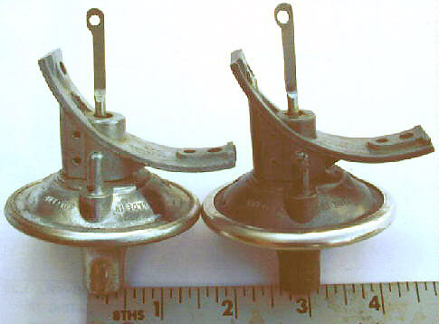
The left vacuum capsule in this picture is a NOS part (Triumph p/n 520131, Lucas p/n 54424241), while the right capsule is a worn version of the same part from a 1973 MkII Stag (US market). Note the elongation of the hole in the actuating rod of the old capsule. Together with wear in the pin that connects the actuating rod to the baseplate, there was so much slop that the vacuum capsule could not reliably retard the timing to its proper setting. This resulted in an occasionally higher than normal idle speed, causing annoying vibration or shaking at idle with both Drive and brakes engaged (when you’re stuck at a traffic light, for example). If you encounter this shaking, try moving the gear selector from Drive to Neutral. If the idle comes up to 1300 rpm (or higher), your vacuum retard is probably not functioning properly. Try slightly opening the throttle to raise the engine speed up to 2000-2500 rpm, then quickly release it so that the throttle snaps closed. If your idle then returns to 800-900 rpm, there’s a good chance that your distributor’s vacuum retard system parts need attention. Remember that if the coolant temperature is above approximately 210F, the vacuum retard is disabled by a thermostatic vacuum switch mounted just under the upper hose connection to the “hot” tank of the radiator. Disabling the vacuum retard causes the spark timing to advance, which will raise the idle speed and increase the coolant flow through the radiator. If the idle speed remains at 1300 rpm or so but only while the coolant temperature is above normal, the vacuum retard is working properly.
by Tim Buja from the Stag Repair Operations Manual
According to my Stag Repair Operations Manual, the head torquing procedure (12.29.27) is as follows:
 -------------------
|D   B   A   C   E  | <--nuts on studs
|                   |
|                   | front of head
|                   |
|I   G   F   H   J  | <--bolts
 -------------------
- Tighten cylinder head nuts as follows: A, B, C, D, E
- Tighten cylinder head bolts as follows: F, G, H, I, J
- Tighten two bolts securing front cover to cylinder head. Tighten 1 and 2 to torque 45 to 55 lbf ft (6.2 to 7.6 kgf m)
Note: Fit cylinder head studs to full depth of thread, finger-tight.
The torque wrench settings in the front of the ROM list the following:
| Cylinder head attachment bolt: | 7/16″ U.N.C. | 7.6 kgf m | 55 lbf ft |
| Cylinder head attachment stud: | 7/16″ U.N.C. | 7.6 kgf m | 55 lbf ft |
| Timing cover to cylinder head: | 5/16″ U.N.F. | 2.8 kgf m | 20 lbf ft |
In addition, the ROM procedure for refitting the cylinder head (12.29.10) specifies a torque figure of 55 lbf ft (7.6 kgf m) for the nuts and bolts, and also includes the following:
- After 1600 kilometers (1000 miles) running, recheck the cylinder head fixings for correct tightness, as follows.
- With the engine cold and working in sequence shown in Operation 12.29.27, slacken each fixing in turn, approximately one flat, then re-tighten to the correct torque figures.
Triumph Stag Repair Operations Manuals are currently available from EWA in New Jersey, USA or directly from the publisher ( Robert Bentley ). I have done an Alta Vista search on “Triumph Stag” and it found a link directly to the Robert Bentley site where you can order the manual as well as the original BL Spare Parts Catalog.
Tim Buja, TKBuja@insightbb.com
80 TR8, 73 Stag, 72 TR6
Updated by Tim Buja
This information may be of help to you in sorting out electrical matters that you may have concerning your Stag. This information was compiled from the Stag Repair Operations Manual electrical drawings and by exploration in my 1973 Mk II Stag (USA market with air conditioning). Remember that there are always discrepancies between the ideal and real worlds… Good Luck!
Quick Index
Stag Fuses and Associated Equipment
Fuse    Size  Fed          Wire    Service
 #      amps  from         color
1-2 35 Battery P “Battery Control”
Horn & horn relay, lighter, puddle lamps, roof (T-Bar) lamp,
console lamps, glovebox lamp, clock, main beam flash, hazard
flashers, boot lamp
3-4 35 Ignition G “Ignition Control”
Switch Fuel gauge, temperature gauge, tach, stop lamps, windscreen
“Ign on” washer pump, reverse lamps, turn signals, seat belt buzzer
5-6 5 Master RB “Parking Lights”
Lighting LH tail lamp, LH front parking lamp
Switch
7-8 10 Master R “Side & Tail Lights”
Lighting RH tail lamp, instrument lights, marker lamps, license plate
Switch lamps, automatic transmission shifter lamp, lighter lamp
9-10 ?? Ignition PG “- Unlabeled -”
Controlled Heated rear screen, A/C compressor clutch,
Relay A/C condensor fans
11-12 25 Main/Dip/ US “Headlights Main Beam “1””
Flash Switch LH Main Beams
13-14 25 Main/Dip/ UW “Headlights Main Beam “2””
Flash Switch RH Main Beams
15-16 10 Main/Dip/ UR “Headlights Dip Beam RH”
Flash Switch RH Dip Beam
17-18 10 Main/Dip/ UK “Headlights Dip Beam LH”
Flash Switch LH Dip Beam
19-20 15 Ignition G “Screen Wiper Motor”
Switch “on” Windscreen wiper motor, wiper delay relay
21-22 25 Ignition PU “Heater Motor”
Controlled A/C microswitch, blower motors, A/C relay,
Relay blower speed change relay
23-24 10 Window Lift Y “Overdrive”
Relay Overdrive
Wire Colors and Functions
B  Black        G  Green        K  Pink         LG Light Green  N  Brown        O  Orange
P  Purple       R  Red          S  Slate        U  Blue         W  White        Y  Yellow
B Ground
G Ignition Aux–from fuse 3-4 or 19-20
N Battery – unfused
P Battery Control – from fuse 1-2
R RH park/tail/side, license plate lights
S Window lift relay to window lift CB & overdrive circuit fuse 23-24
U Headlight feed to main/dip/flash switch
W Ignition Switch “Ign on”
Y Fuse 23-24 to overdrive switch
BP Brake differential pressure (PDWA) switch to brake warning light
BG Key buzzer to ignition key contact
BW Handbrake switch to handbrake warning light
GB Fuel sender to gauge
GLG Gearbox/seat belt switch to LH belt switch & RH seat switch
GN Reverse light switch to lights
GO Low fuel sender to low fuel warning light
GP Brake light switch to lights
GR LH turn signal
GS A/C cars: Blower switch to blower speed change relay – energized for low speed
Heater cars: Blower switch “high speed” feed to blower motor
GU Temp sender to gauge
GW RH turn signal
GY A/C cars: Blower motors to blower switch
Heater cars: Blower switch “low speed” feed to low speed resistor
KW Ballast resistor wire to ignition coil
LGB Washer pump from steering column switch
LGK Hazard flasher unit to hazard switch
LGN Turn flasher unit to steering column switch & hazard switch
LGO LH belt switch & RH belt switch to Fasten Belt light, to key buzzer thru a diode
LGS Hazard switch to turn flasher
NLG Wiper park switch, delay relay circuit
NR Ignition switch “off” to vent valve solenoid
NY Ignition warning light to alternator field
PB Horn switch to relay
PK A/C relay to heated rear screen switch
PLG A/C microswitch to A/C relay & blower switch (starts blowers on low speed)
PN Ignition controlled relay to fuses 9-10 & 21-22
PO Interior light switch to RH console and roof lamps
PR RH door pin switch to RH puddle lamp & interior light switch
PS LH door pin switch to LH puddle lamp & interior light switch, to key buzzer thru a diode
PU Blower motor & A/C relay circuit feed from fuse 21-22
PW Interior light switch to LH console & roof lamps, boot lamp circuit, glovebox lamp circuit
PY Horn relay to horns
RB Fuse 5-6 to LH front park lamp, LH tail lamp
RG LH parking lamp supply from master light switch, to ign switch to feed RH lamps w/ ign on
RLG Wiper normal speed
RO Fuse 7-8 to RH tail lamp, RH front park lamp, instrument lights, front marker lamps
RW Dash panel lights from rheostat
RY Front fog light feed from master light switch
SB A/C relay to condenser fans & high pressure cutout switch
SG Window lift CB to window lift switches, RH window lift switch to RH window lift motor
SN LH window lift switch to LH window lift motor
SO A/C high pressure cutout switch to A/C compressor clutch
SP RH window lift switch to RH window lift motor
SU LH window lift switch to LH window lift motor
SW RH blower motor to blower motor speed change relay
SY A/C relay to thermostat
UK LH dip beam
ULG Wiper high speed
UR Main/Dip/Flash switch to fuse 15-16 & 17-18, fuse 15-16 to RH dip beam
US LH main beams
UW Main/Dip/Flash to fuse 11-12 & 13-14, main beam warning lamp, fuse 13-14 to RH main beams
WG Heated rear screen switch to heated rear screen & warning lamp
WK Ignition Switch “Acc” – radio feed
WLG Wiper delay circuit
WN Oil pressure sender to light
WP Vent valve solenoid to oil pressure switch
WR Ignition Switch “Start” through auto trans inhibit switch to starter solenoid
WS Tach signal from ignition coil negative terminal
WU Choke cable switch to choke warning light
WY Starter solenoid to ignition coil–supplies full voltage to coil while cranking
YP Overdrive switch through overdrive gearbox switch to overdrive solenoid
B Black G Green K Pink LG Light Green N Brown O Orange
P Purple R Red S Slate U Blue W White Y Yellow